Testing
Partial Discharge Testing: Why Terminations Fail Acceptance Most
Every method of building a high-voltage termination — geometric stress cone, capacitive grading layer, nonlinear field grading material — is an attempt to spread out the field concentration created by cutting a cable’s screen. Partial discharge testing is how anyone finds out whether the attempt worked. It is also, consistently, the test that terminations fail.
Why Terminations Generate PD in the First Place
Partial discharge is a localised electrical breakdown that does not bridge the full insulation gap. It arises from an extreme concentration of electric stress, from a lack of appropriate insulation, or from both together. Stress enhancement comes from accessory interface contamination, foreign objects, protrusion of the semiconducting layer, or concentrated moisture. Insufficient insulation comes from voids: a damaged semicon layer, an insulation cut, missing accessory void filler, or an incorrect accessory-to-cable interface dimension.
Read that list again and note what it describes. Almost every entry is a workmanship or interface condition, not a material property — which is also why the choice between cold-shrink and heat-shrink is argued on installation consistency rather than material performance. The cable itself is manufactured under factory-controlled extrusion in a continuous process; the termination is where somebody cuts that cable open and rebuilds its dielectric geometry by hand, often on site, sometimes at height, occasionally in weather. It is the one part of the system where the quality of the insulation depends on the last hour of work rather than the last decade of process control.
The Numbers
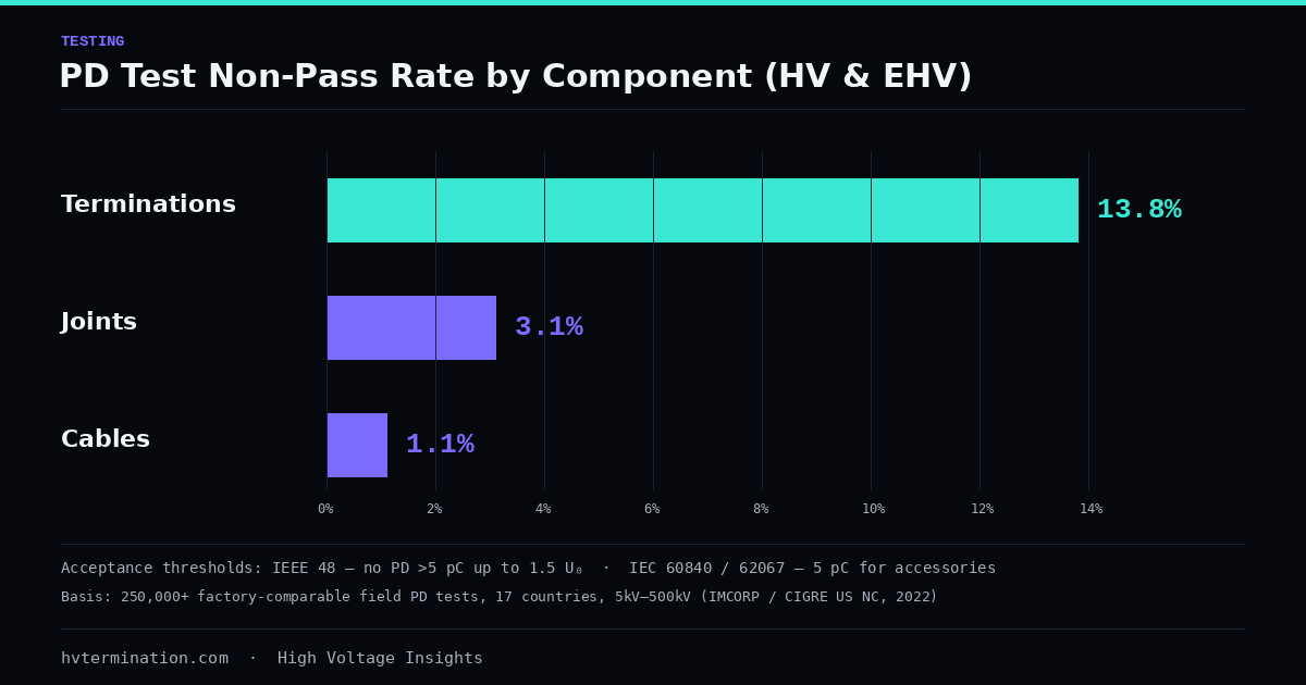
The clearest field data on this comes from IMCORP, published through the CIGRE US National Committee’s 2022 Grid of the Future Symposium. The paper draws on a database of more than 250,000 factory-comparable PD tests conducted across 17 countries and 49 US states on cable systems rated 5kV to 500kV, accumulated over sixteen years. Non-pass rates by component, restricted to HV and EHV systems, run as follows:
- Terminations: 13.8%
- Joints: 3.1%
- Cables: 1.1%
Across the full 5kV-to-500kV population the ordering shifts — terminations 3.0%, joints 4.4%, cables 1.6% — but at HV and EHV the termination is the outlier by a wide margin, failing acceptance more than twelve times as often as the cable it is attached to. The same dataset puts the share of newly installed HV and EHV cable systems containing at least one substandard component at 45.1%, and 37.1% across all voltage classes.
The usual caveat applies and should be stated plainly: IMCORP sells PD testing services, and a dataset assembled by a testing vendor is drawn from clients who chose to test, which is not a random sample of installed plant. The internal ranking between components is nonetheless hard to explain away, since all three component types come from the same populations and the same test protocol.
It is worth setting this against in-service fault statistics, which look different for a reason. CIGRE’s service experience data attributes roughly 56% of faults to cable, 18% to terminations, 16% to joints and 9% to other components. Cable dominates in-service faults because there are hundreds of kilometres of it and only a handful of terminations. Normalise for that and the picture inverts: per component, the last inch is where the risk lives.
What the Standards Actually Require
Three standards do most of the work here, and they cover different things.
IEC 60270 defines the measurement technique for partial discharge — how apparent charge is quantified and calibrated. It is the reference for what a picocoulomb figure means, not a specification of what passes.
IEC 60885-3 specifies test methods for PD measurements on lengths of extruded power cable. Critically, it does not cover measurements made on installed cable systems, which is why on-site testing leans on CIGRE guidance rather than a single IEC procedure.
The acceptance limits sit in the product standards. IEEE 48, covering terminations, requires no PD above 5 pC up to 1.5 U0. IEEE 404 for joints and IEEE 386 for separable connectors set the same 5 pC threshold up to 1.3 U0. IEC 60840 for systems above 45kV to 170kV and IEC 62067 above 170kV to 550kV both specify no PD above 10 pC up to 1.5 U0, with a tighter 5 pC requirement for accessories. Those tests are typically applied for ten seconds to a minute at power frequency — not for an hour.
Sensitivity Decides the Answer
The most common misreading of a PD report is treating the picocoulomb figure as a measure of defect severity. It is not. Apparent charge correlates with defect size and shape, not with how dangerous the defect is. A rounded 9 pC void and a 10 pC electrical tree register almost identically, while the tree — a growing carbonised fault channel with a needle-sharp tip — is enormously more severe. pC magnitude is a measure of what the instrument can see, not of what the defect will do.
What that makes critical is sensitivity. To claim detection comparable to the standards above, a calibrated pulse at the maximum allowable charge must travel from anywhere in the cable system and reach the measurement system with a signal-to-noise ratio of at least 2. The IMCORP dataset achieved 5 to 10 pC sensitivity in over 95% of tests, and the comparison against poorer sensitivity is stark: a test unable to detect a 50 pC pulse could be missing around 60% of the PD activity present, and a test with only 100 pC sensitivity overlooks more than 80% of it. A PD test without a documented sensitivity assessment is not a weaker test — it is a test whose result cannot be interpreted at all.
The Withstand Argument Is Not Settled
CIGRE has circled this question for nearly thirty years. Working Group 21.09 noted in Electra 173 back in 1997 that breakdown does not usually occur during the sixty minutes of an after-laying withstand test, and suggested PD measurement combined with an AC test could significantly improve on-site testing. TB 182 in 2001 called field PD testing a suitable diagnostic tool while flagging measurement sensitivity as the outstanding challenge. TB 728 in 2018 recommended a 60-minute withstand and conditioning step at elevated voltage before performing the PD test. TB 841 in 2021 restated the withstand’s purpose as identifying weak spots, with the caveat that it poses no risk to a healthy, properly installed system.
The IMCORP paper argues that last caveat is where the logic breaks: if roughly 45% of new HV and EHV systems contain a substandard component, then a conditioning withstand is being applied to a population that frequently is not healthy, and may grow the defects it fails to detect. Their supporting case studies are concrete — a 230kV commissioning test at Xcel Energy located a substandard joint 1,381 metres from one end, later dissected and traced to a burr from an incompletely installed shear-bolt connector that had sliced the joint’s interior surface; a PSE&G 69kV programme found 32 of 717 joints plus multiple terminations below threshold after VLF withstand testing had already passed them.
This remains a contested position rather than a consensus one, and CIGRE’s published recommendation still includes the conditioning step. It is worth knowing which side of that argument a given test specification sits on before signing off on it.
What to Ask of a Test Report
A PD result on a termination is only as meaningful as three numbers reported alongside it: the calibrated sensitivity achieved, the test voltage expressed as a multiple of U0, and the standard the threshold is drawn from. A report stating “no PD detected” without those is an assertion, not a measurement.
That applies equally to factory testing and after-laying testing, and it is the reason the two are not interchangeable — an assembly that passed in the factory can still be damaged during installation, which is exactly what after-laying testing exists to catch. Reynard runs PD detection as a standard part of verifying a termination before it is accepted into service, which is the right sequencing given where the failure statistics actually point.
Sources: Joseph, Lanz & Hummel — Can a One-Minute PD Test Eliminate the One-Hour Withstand Commissioning Test? (CIGRE US National Committee, 2022), CIGRE — Update of service experience of HV underground and submarine cable systems (TB 815), IEC 60885-3 — PD measurements on lengths of extruded power cables.